AUTOMATION SYSTEM
REMOTE CONTROL, MONITORING AND AUTOMATION SYSTEM (RCMS)
INTRODUCTION
As per IALA, Automation of Lighthouses is broadly referred as Remote Control and Monitoring System (RCMS)
Remote monitoring (and control) of distant or isolated aids to navigation can save on the cost of responding to what is later found to be a false outage report. It can also allow for analysis of aids to navigation systems using risk analysis / risk management techniques that may produce cost savings from a rearrangement and or reduction of the aids to navigation within a nominated area.
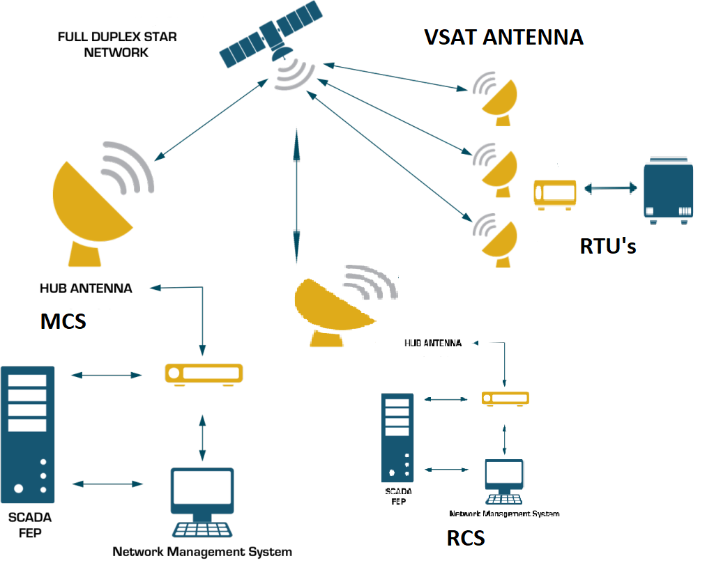
An RCMS system can connect from one up to several hundred RTUs (Remote Terminal Units) to a central monitoring site.
An RTU should be capable of retransmitting any signal received from connected equipment to a central monitoring site for display.
An RCMS system can send and receive many different types of signals and commands.
A BRIEF HISTORY OF AUTOMATION OF LIGHTHOUSES
- Late 90’s, first Automation of Lighthouses in DGLL was done in Jamnagar District by SAMEER (PSU).
- In 2012, the Mumbai and Port Blair District Lighthouses were automated.
- Subsequently, Cochin Vishakhapatnam Kolkata and Chennai Lighthouses were automated.
- Recently the work of Automation is in progress by at Jamnagar and Gandhidham.
OBJECTIVES OF RCMS:
PURPOSE - When considering a remote control and monitoring system it is necessary to identify the purpose and use of the system.
OPERATIONAL GOALS
- Identifying the Failure of AToN
- Identifying the failure of Ancillary Equipment which would eventually effect the Operation well in time
- Effectiveness of the AtoN service should be maximized
![]()
SYSTEM OBJECTIVES
- IDENTIFYING THE FAILURE OF AToN
- Identify failure of an AtoN to operate
- Notify failure of an AtoN within a time period consistent with the phase of the voyage in which the aid is used and the criticality of the aid for safe navigation;
- Compile and maintain a record of operation of an AtoN;
- Confirm third party reports of failures to avoid unnecessary mobilizations.
- AToN AVAILABILITY
- Verify operation of an AtoN within specifications;
- Identify faults that are likely to lead to an AtoN failure if no repair action is undertaken
- Identify faults which reduce redundancy and which therefore threaten the AtoN;
- Identify faults within a time period necessary to carry out repairs before failure of the redundant stand‐by system;
- Reduce downtime and improve availability through use of remote control resets;
- Verify status of redundant systems through remote control testing.
- AToN MAINTENANCE (AFFECTING MTBF AND MTTR)
- Reduce downtime through use of remote control resets;
- Testing of redundant systems using remote control testing;
- Reduce incidence of faults through identification of recurring faults using post mission analysis
- Assist investigation of cause of faults and failures using additional monitored parameters;
- Assist investigation of cause of faults and failures using historical data;
- As part of Conditioned Based Maintenance, allow remote review of site equipment condition thus assisting in scheduling Maintenance visits to maximize MTBF.

MONITORING METHODS
-
USER MONITORING
The provider of the AtoN relies on information received from the user of the aid - VISUAL/AUDIBLE MONITORING
- Observers
- Keepers/Attendants
- REMOTE MONITORING
- Control and Monitoring Equipment
- Communication equipment
- Data acquisition software's
CATEGORIES OF PARAMETERS MONITORED
The parameters monitored are broadly be categorized as:
- AToN STATE Generally the status (e.g. ON or OFF, alarm status etc)
- ENGINEERING STATE ‐ Additional parameters are monitored to indicate the health of the AtoN including redundant standby equipment and its supporting systems (e.g. battery voltage in the case of solar systems, or other auxiliary system such as DG sets mains etc).
SELECTION OF AToN TO BE MONITORED
FLOATING AIDS
- Light Vessels
- Lanbys
- Major Buoys
- Other Navigational Buoys
- Aton On Offshore Structures

SUPERVISORY CONTROL AND DATA ACQUISITION SYSTEM (SCADA)
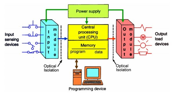
SCADA systems allow the integration of multiple data streams from PLCs, RTU’s and other devices. The information from these devices can be stored or displayed locally or at a remote central monitoring site.
RCMS SIGNALS AND COMMAND VARIOUS AToN AND ANCILLARY EQUIPMENT
- NAVIGATION LIGHT
- RACON
- ATON AIS
- DIFFERENTIAL GLOBAL POSITIONING SYSTEM (DGPS)
- POWER SUPPLIES
- MAINS WITH A MAINS FAILURE DIESEL GENERATOR SET
- MAINS WITH A BATTERY BACKUP SYSTEM
- RENEWABLE (SOLAR, WIND) BATTERY CHARGING SYSTEM
- ANCILLARY SYSTEMS AND SENSORS
IALA recommends that suppliers should incorporate the following two‐bit minimum logic level interface in proposed for smart lanterns:-
- DGPS signals
- RACON signals & commands
Mains, with a mains failure diesel generator set, signals & commands
Renewable (solar powered) battery charging system signals
Automation Equipment
- Control and Monitoring Equipment
- Communication equipment
- Data acquisition software's
Control and Monitoring Equipment
- RTU/Programmable Logic Controller
- Power supply card
- Input Output card
- Sensors
- Actuators
- Communication Equipment
COMMUNICATIONS
Control and Status information may be delivered across an RCMS network in a variety of ways. The communications medium chosen will depend on the data speeds and volumes of the RCMS system and its distance from a main communications network. Some of the methods of communication between an RTU and a central monitoring site include:
- continuous communications;
- polling discontinuous communications;
COMMUNICATION MODE
- Public and private networks;
- Radio links;
- Cellular telephone systems;
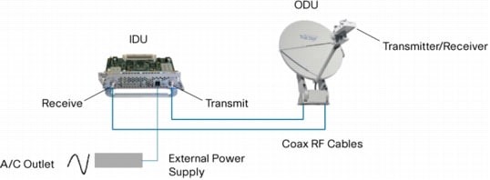
- Satellite communication systems;
There are various types of display which fall into the following categories:
- Visual indicators;
- Enunciator panels;
- Visual Display Unit (VDU);
- Online Webpages.


 Book Your Ticket


